Testimonials
-
Address: Sydney
Australia, NSW 2000 -
Call Us: 0481 354 764
pawel@vigilantia.com.au
Address: Sydney
Australia, NSW 2000
Call Us: 0481 354 764
pawel@vigilantia.com.au
Nondestructive testing (NDT) is any of a wide group of analysis techniques used in science and technology industry to evaluate the properties of a material, component or system without causing damage.
Visual Testing (VT), also known as Visual Inspection, is a non-destructive testing (NDT) method used to assess the surface condition, appearance, and overall integrity of an object or material. It is one of the most basic and widely used NDT techniques, aiming to detect surface defects, discontinuities, and abnormalities without causing any harm to the tested material. Key characteristics of Visual Testing include: Non-Destructive: Visual Testing is a non-intrusive technique, meaning it does not alter or damage the material being inspected. This is particularly useful when testing delicate or expensive components. Surface Inspection: VT focuses on the outer surface of an object. It's effective for identifying flaws that are readily visible, such as cracks, corrosion, pits, weld discontinuities, scratches, dents, and other irregularities. Direct Observation: Inspectors rely on their trained eyes to visually detect irregularities. The process involves looking for indications of defects and anomalies using tools such as handheld lights, mirrors, magnifying lenses, and even remote visual devices like borescopes and videoscopes. Qualitative Analysis: VT primarily provides qualitative information about the condition of the material. Inspectors determine whether a detected anomaly is acceptable according to predefined criteria, standards, or specifications. Human Judgment: Visual Testing heavily depends on the skills and experience of the inspector. Proper training and experience are crucial to accurately identify defects and make appropriate judgments. Wide Range of Applications: VT is employed across various industries, including manufacturing, construction, aerospace, automotive, maritime, and more. It's used to inspect welds, structural components, pipelines, pressure vessels, machinery, electronic components, and more. Limited Depth of Inspection: One limitation of VT is that it can only detect surface-level defects. Deeper or subsurface anomalies may not be detected using this method alone. Supporting Technologies: While VT is primarily a visual process, it can be enhanced by using technologies such as digital photography, thermography (to detect temperature variations), and videoscopes or borescopes (for inspecting confined spaces and internal components). Documentation: VT inspections are often documented through photographs, videos, sketches, and written reports. This documentation is essential for quality control, record-keeping, and compliance with industry regulations. In summary, Visual Testing (VT) is a fundamental non-destructive testing technique that involves direct visual observation of the surface of an object to identify surface defects and discontinuities. It plays a critical role in ensuring the safety, reliability, and quality of various materials and components in a wide range of industries.
Penetrant Testing (PT), also known as Dye Penetrant Testing (DPT) or Liquid Penetrant Testing (LPT), is a widely used non-destructive testing (NDT) method for detecting surface defects and discontinuities in materials. This technique is particularly effective for identifying cracks, porosity, laps, leaks, and other open-to-surface flaws that may not be visible to the naked eye. Penetrant Testing is commonly used in industries such as aerospace, automotive, manufacturing, and construction. Here's an overview of how Penetrant Testing works: Pre-cleaning: The surface of the material being tested is thoroughly cleaned to remove any contaminants such as dirt, grease, oil, and paint. Proper cleaning is crucial as it ensures that the penetrant can effectively enter and highlight any defects. Application of Penetrant: A liquid penetrant, which is a colored or fluorescent dye, is applied to the surface of the material. This penetrant is chosen based on its compatibility with the material and the type of defect being sought. Dwell Time: The penetrant is allowed to dwell on the surface for a specific period, known as the dwell time. During this time, the penetrant seeps into any surface cracks or defects through capillary action. Excess Penetrant Removal: After the dwell time, the excess penetrant on the surface is carefully removed using a cleaning agent or by rinsing. However, the penetrant trapped within defects remains. Application of Developer: A developer, often in the form of a white powder or a liquid, is applied to the surface. The developer acts as an absorbent that draws the trapped penetrant out of the defects and spreads it on the surface. Indication Inspection: The surface is visually inspected under appropriate lighting conditions. Any trapped penetrant that has been drawn out of defects by the developer forms visible indications on the surface. These indications are often bright colored against the developer or fluoresce under ultraviolet (UV) light when fluorescent penetrants are used. Interpretation: The inspector evaluates the indications based on their size, shape, color, and location. Experienced inspectors can differentiate between acceptable surface conditions and indications that suggest defects or anomalies. Documentation: The inspection results, including the location and nature of any indications, are documented. This documentation is essential for quality control, record-keeping, and compliance with industry standards and regulations. Key advantages of Penetrant Testing include its ability to detect very fine surface cracks and its relative simplicity and cost-effectiveness. However, it is limited to detecting surface-level defects and may not be suitable for materials with rough surfaces or intricate geometries. In summary, Penetrant Testing (PT) is a non-destructive testing method that involves applying a penetrant to the surface of a material, allowing it to seep into defects, and then using a developer to draw out and highlight any trapped penetrant. This technique is used to detect surface-level defects and discontinuities in a variety of materials and components.
Magnetic Particle Testing (MT), also known as Magnetic Particle Inspection (MPI), is a non-destructive testing (NDT) method used to detect surface and near-surface defects in ferromagnetic materials. Ferromagnetic materials are those that can be magnetized, such as iron, steel, and nickel. MT is particularly effective for identifying flaws such as cracks, porosity, weld discontinuities, and other defects that are oriented perpendicular to the magnetic field. Here's an overview of how Magnetic Particle Testing works: Magnetization: The object or component to be inspected is magnetized using either a direct current (DC) or an alternating current (AC) magnetic field. This magnetization creates lines of magnetic flux within the material. Application of Magnetic Particles: A fine magnetic powder, often in the form of iron particles coated with a fluorescent or colored pigment, is applied to the surface of the magnetized material. These particles are attracted to the areas of magnetic flux leakage caused by defects on or near the surface. Indication Formation: The magnetic particles accumulate and form visible indications or patterns around the areas of magnetic flux leakage. These indications highlight the presence of surface or near-surface defects. Inspection: The surface is visually examined under appropriate lighting conditions. The accumulated magnetic particles create a contrast between the background material and the indications, making it easier to detect defects. Interpretation: Inspectors evaluate the size, shape, and location of the indications to determine the nature and severity of defects. Experienced inspectors can differentiate between acceptable conditions and indications caused by defects. Demagnetization: After inspection, the magnetization is usually removed from the material. Demagnetization can be achieved using techniques such as reversing the current direction or using a demagnetizing coil. Documentation: The inspection results, including the location and nature of any indications, are documented. This documentation is crucial for quality control, record-keeping, and compliance with industry standards. Magnetic Particle Testing can be performed using two primary techniques: Dry Particle Testing: Dry magnetic particles are applied directly to the surface of the test object. They adhere to areas of magnetic flux leakage, forming visible indications. Wet Particle Testing: Wet magnetic particles are suspended in a liquid solution and applied to the surface. The liquid helps the particles spread evenly and provides better mobility for finding defects. Key advantages of Magnetic Particle Testing include its sensitivity to surface and near-surface defects, its relatively quick and easy application, and its ability to inspect complex shapes and sizes of components. However, it is limited to ferromagnetic materials and is primarily effective for detecting defects perpendicular to the magnetic field. In summary, Magnetic Particle Testing (MT) is a non-destructive testing method that involves magnetizing a ferromagnetic material and applying magnetic particles to its surface. The particles accumulate around defects, forming visible indications that help identify surface and near-surface defects. This technique is commonly used in industries involving metal fabrication, manufacturing, aerospace, and more.
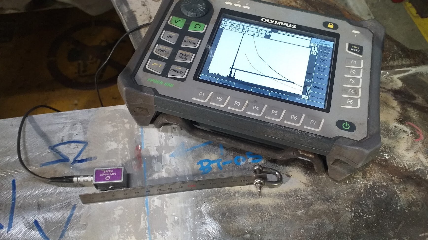
Ultrasonic Testing (UT) is a versatile and widely used non-destructive testing (NDT) method for evaluating the integrity and quality of materials and components. This technique utilizes high-frequency sound waves (ultrasonic waves) to detect and characterize internal flaws, discontinuities, and thickness variations within a wide range of materials. UT is particularly effective for identifying defects such as cracks, voids, delaminations, and inclusions. Here's an overview of how Ultrasonic Testing works: Principle of Sound Waves: Ultrasonic waves are mechanical vibrations with frequencies above the audible range of human hearing (typically above 20 kHz). In UT, a transducer generates these waves and directs them into the material being inspected. Transducer and Coupling: A transducer, typically made of piezoelectric crystals, emits ultrasonic waves and also receives the waves after they have traveled through the material. A coupling medium (usually a gel or water) is used to ensure efficient transmission of the waves between the transducer and the material's surface. Propagation and Reflection: Ultrasonic waves propagate through the material until they encounter a boundary between different materials or a defect within the material. When the waves encounter such boundaries, a portion of the waves is reflected back to the transducer. Receiving and Interpretation: The transducer detects the reflected waves and converts them into electrical signals. The time taken for the waves to travel to the boundary and back is used to calculate the distance to the boundary or defect. The amplitude and time-of-flight of the returned waves provide information about the size, shape, and nature of the defects. Display and Analysis: The signals are displayed on a screen in the form of a waveform called an ultrasonic A-scan. Inspectors analyze the A-scan patterns to identify and characterize defects. Modern equipment often provides B-scan or C-scan images, which offer cross-sectional or planar views of the inspected object, respectively. Calibration and Standards: UT systems are calibrated using reference standards with known defect sizes and properties. This calibration ensures accurate interpretation of the inspection results. Thickness Measurement: UT is also widely used for measuring material thickness. By analyzing the time taken for an ultrasonic wave to travel through a material and return, inspectors can determine the material's thickness. Documentation: The inspection results, including the detected defects, their sizes, locations, and relevant characteristics, are documented. This documentation is essential for quality control, record-keeping, and compliance with industry standards. Ultrasonic Testing can be performed using various techniques, such as: Pulse-Echo Technique: The most common UT technique, where the same transducer generates and receives the ultrasonic waves. Through-Transmission Technique: Uses two transducers—one emits the waves, and the other receives them. This technique is particularly useful for detecting defects that are parallel to the surface. Phased Array Ultrasonics (PAUT): Involves using an array of transducers that can be electronically controlled to steer and focus the ultrasonic beam, allowing for more detailed inspections. Time-of-Flight Diffraction (TOFD): A specialized technique that measures the diffracted waves from defect edges to accurately determine their sizes. UT is valued for its ability to penetrate materials deeply, its sensitivity to small defects, and its capability to provide precise thickness measurements. It is used in a wide range of industries, including manufacturing, construction, aerospace, energy, and more. In summary, Ultrasonic Testing (UT) is a non-destructive testing method that uses high-frequency sound waves to detect internal defects and evaluate material thickness. It offers detailed information about the size, shape, and location of defects within materials and is essential for ensuring the quality and reliability of various components and structures.
Eddy Current Testing (ET) is a non-destructive testing (NDT) technique used to assess the integrity of conductive materials by exploiting the principle of electromagnetic induction. This method is particularly effective for detecting surface and near-surface defects, as well as for measuring material thickness and conductivity variations. Eddy Current Testing is commonly used in industries such as aerospace, automotive, manufacturing, and electronics. Here's an overview of how Eddy Current Testing works: Principle of Electromagnetic Induction: When an alternating current (AC) is passed through a coil or conductor, it generates a magnetic field around it. When this coil or conductor is brought close to a conductive material, the changing magnetic field induces eddy currents (circular currents) within the material. Eddy Current Probe: In Eddy Current Testing, a probe consisting of a coil is placed near the surface of the material being inspected. The coil is typically encased in a non-conductive housing to focus the magnetic field on a specific area. Eddy Current Interaction: The eddy currents interact with the material's electrical conductivity, as well as with any defects or variations present in the material. These interactions affect the impedance (resistance to the flow of alternating current) of the coil. Detection and Analysis: The impedance changes are measured by the eddy current instrument. Changes in impedance are related to the material's characteristics and the presence of defects. The instrument displays these changes as a waveform called an eddy current signal. Signal Interpretation: Skilled inspectors analyze the eddy current signal patterns to detect and characterize defects such as cracks, corrosion, pitting, and changes in material properties. The amplitude, phase, and frequency components of the signal provide information about the size, shape, and depth of defects. Sorting and Sorting: Eddy Current Testing can also be used for material sorting and grading based on electrical conductivity variations. This is particularly useful for sorting alloys and verifying heat treatment. Material Thickness Measurement: ET can be used to measure the thickness of conductive materials by assessing the changes in impedance as the probe is brought closer to the material. Probe Types: Different types of eddy current probes can be used, such as absolute probes (which provide a direct measurement of conductivity) and differential probes (which compare two areas for differences in conductivity). Documentation: Inspection results, including the detected defects, their characteristics, and relevant data, are documented for quality control, record-keeping, and compliance with industry standards. Eddy Current Testing offers several advantages, including its ability to quickly inspect large areas, its sensitivity to surface and near-surface defects, and its capability to differentiate between subtle material variations. However, it is limited to conductive materials and is less effective for non-metallic materials. In summary, Eddy Current Testing (ET) is a non-destructive testing method that utilizes electromagnetic induction to generate eddy currents within conductive materials. By analyzing the interactions between these currents and the material's properties, inspectors can detect defects, assess material characteristics, and measure thickness. ET is widely used across industries where conductive materials are used and plays a crucial role in ensuring the quality and reliability of various components and structures.
Radiographic Testing (RT), also known as X-ray Radiography or Industrial Radiography, is a non-destructive testing (NDT) method used to inspect the internal structure of materials and components using X-rays or gamma rays. This technique is particularly effective for detecting internal defects, discontinuities, and anomalies in various materials, including metals, plastics, ceramics, and composites. RT is widely used in industries such as manufacturing, construction, aerospace, and energy. Here's an overview of how Radiographic Testing works: X-ray or Gamma Ray Source: In RT, a controlled source of X-rays or gamma rays is used to generate penetrating radiation. X-ray generators and radioactive isotopes (such as iridium-192 or cobalt-60) are commonly used as radiation sources. Radiographic Exposure: The material or component to be inspected is placed between the radiation source and a detector (usually a radiographic film or a digital detector). The radiation penetrates the material and interacts with the internal structures. Attenuation and Absorption: As the radiation passes through the material, it is attenuated (weakened) and absorbed differently by various materials and internal features. Areas with different densities, such as defects, voids, and inclusions, attenuate the radiation differently from the surrounding material. Image Formation: The radiographic film or digital detector records the intensity of the radiation that reaches it after passing through the material. The resulting image is a radiographic image, often referred to as a radiograph. Film Processing or Digital Imaging: If using film, the exposed film is developed and processed to create a visible image. In digital radiography, the digital detector converts the radiation intensity into a digital image file. Image Interpretation: Skilled inspectors analyze the radiographic image to detect and characterize defects such as cracks, voids, porosity, and inclusions. The size, shape, and location of these features can be evaluated based on the radiographic contrast. Image Quality: The quality of the radiograph is influenced by factors such as exposure settings, radiation energy, film or digital detector sensitivity, and the thickness and density of the inspected material. Safety Measures: Radiographic Testing involves the use of ionizing radiation, which can be hazardous to health if not properly controlled. Strict safety protocols are followed to ensure the safety of both the personnel and the environment. Documentation: Inspection results, including the radiographs, defect locations, and other relevant data, are documented for quality control, record-keeping, and compliance with industry standards. Radiographic Testing offers several advantages, including its ability to provide detailed internal views of components, its sensitivity to a wide range of defects, and its capability to inspect complex geometries. However, it requires specialized equipment, safety precautions, and skilled personnel. In summary, Radiographic Testing (RT) is a non-destructive testing method that uses X-rays or gamma rays to inspect the internal structure of materials and components. It helps detect and characterize internal defects and discontinuities, making it a valuable tool for ensuring the quality and integrity of various industrial products and components.
Phased Array Ultrasonic Testing (PAUT) is an advanced non-destructive testing (NDT) technique that utilizes an array of ultrasonic transducers to improve the accuracy and efficiency of inspections. PAUT is particularly effective for detecting and characterizing flaws, such as cracks, voids, and inclusions, in various materials. This technique allows for better control over the ultrasonic beam, enabling inspections of complex geometries and providing valuable data for industries such as manufacturing, aerospace, and energy. Here's an overview of how Phased Array Ultrasonic Testing (PAUT) works: Array of Transducers: PAUT employs a probe containing multiple ultrasonic transducers that are individually controlled. The transducers are usually arranged in a linear or matrix array. Each transducer can emit ultrasonic waves at a precise angle and time delay. Controlled Beam Steering: By varying the timing and amplitude of the ultrasonic pulses emitted by each transducer, the direction of the ultrasonic beam can be controlled. This allows for the creation of complex beam profiles, including focused beams, angles, and even sweeping beams. Beam Focusing: PAUT can focus the ultrasonic energy at a specific depth within the material being inspected. This ensures that the energy is concentrated in the region of interest, improving flaw detection and characterization. Sensitivity and Resolution: The control over beam angles and focusing enhances sensitivity to specific flaws and provides high-resolution imaging. This makes PAUT particularly effective for detecting small defects or variations in complex components. Inspection Setup: The PAUT probe is placed on the material's surface, and the transducers emit ultrasonic waves that propagate into the material. The reflected waves from internal features or defects are received by the same transducers and recorded for analysis. Data Acquisition and Imaging: The received signals are processed by a computerized ultrasonic instrument. The instrument calculates the time of flight and amplitude of the received signals and creates a visual representation, often referred to as a B-scan or C-scan image. Image Interpretation: Skilled inspectors analyze the B-scan or C-scan images to detect and characterize defects. The images provide valuable information about the location, size, and orientation of flaws within the material. Advantages: PAUT offers several advantages, including its ability to inspect complex geometries, its high-resolution imaging, its ability to perform multiple inspections in a single scan, and its improved accuracy compared to conventional ultrasonic testing. Documentation Inspection results, including images and flaw data, are documented for quality control, record-keeping, and compliance with industry standards. PAUT is commonly used in a wide range of applications, including weld inspection, corrosion assessment, and flaw detection in critical components. It is particularly beneficial for applications that require a high level of accuracy, such as aerospace and nuclear industries. In summary, Phased Array Ultrasonic Testing (PAUT) is an advanced NDT technique that uses an array of controlled ultrasonic transducers to improve flaw detection and characterization. Its precise beam control, focusing capabilities, and high-resolution imaging make it a powerful tool for inspecting a variety of materials and components.
Time-of-Flight Diffraction (TOFD) is an advanced non-destructive testing (NDT) technique used to detect and size flaws in welds and other structures with high accuracy. TOFD is particularly effective for detecting planar flaws, such as cracks, lack of fusion, and incomplete penetration, in welds and other components. It's known for its precision and reliability, making it a valuable tool in industries such as oil and gas, nuclear, and aerospace. Here's an overview of how Time-of-Flight Diffraction (TOFD) works: Principle of Diffraction: TOFD is based on the principle of ultrasonic wave diffraction. When an ultrasonic wave encounters the tip of a flaw or defect, it diffracts around the flaw's edges. This diffracted wave creates a distinct signal that can be measured and analyzed. Setup: TOFD typically involves the use of two ultrasonic probes—one acting as a transmitter and the other as a receiver. The probes are positioned on opposite sides of the material being inspected, with the sound waves propagating through the material. Ultrasonic Pulses: The transmitter probe emits a short burst of ultrasonic waves that travel through the material and encounter any flaws in their path. Diffracted Waves: When the ultrasonic waves encounter the edges of a flaw, they diffract and produce diffraction signals. These signals are captured by the receiver probe, which is placed at a specific distance from the transmitter probe. Time Measurement: The time taken for the diffracted signals to travel from the flaw tip to the receiver probe is measured. This time measurement is highly accurate and provides information about the flaw's position and size. Data Analysis: The recorded time measurements are processed to create a visual representation known as a TOFD image or scan. The horizontal axis of the image corresponds to the distance between the probes, while the vertical axis represents the time of flight. Flaws are identified as vertical lines on the image, and their heights correspond to their sizes. Interpretation: Skilled inspectors analyze the TOFD image to assess the position, size, and orientation of the detected flaws. The technique is highly accurate, making it possible to accurately size even small flaws. Advantages: TOFD offers several advantages, including its ability to provide accurate flaw sizing, its sensitivity to planar defects, its minimal need for probe scanning, and its ability to inspect a wide range of materials. Documentation: Inspection results, including TOFD images and relevant flaw data, are documented for quality control, record-keeping, and compliance with industry standards. TOFD is widely used as an adjunct or complementary technique to other ultrasonic testing methods, enhancing the overall accuracy and reliability of flaw detection and sizing. It's especially well-suited for detecting defects in welds, as it provides detailed information about the dimensions and locations of flaws, contributing to improved decision-making in terms of repair and maintenance. In summary, Time-of-Flight Diffraction (TOFD) is an advanced non-destructive testing method that utilizes the diffraction of ultrasonic waves around flaws to detect and accurately size planar defects in materials and welds. Its precision and ability to provide detailed flaw information make it a valuable tool for ensuring the integrity of critical components in various industries.
The relationship between the mind and body is complex.
Provide best testing solutions for your assets.
Internal Quality Audits
Quality Control and Assurance
Testimonials